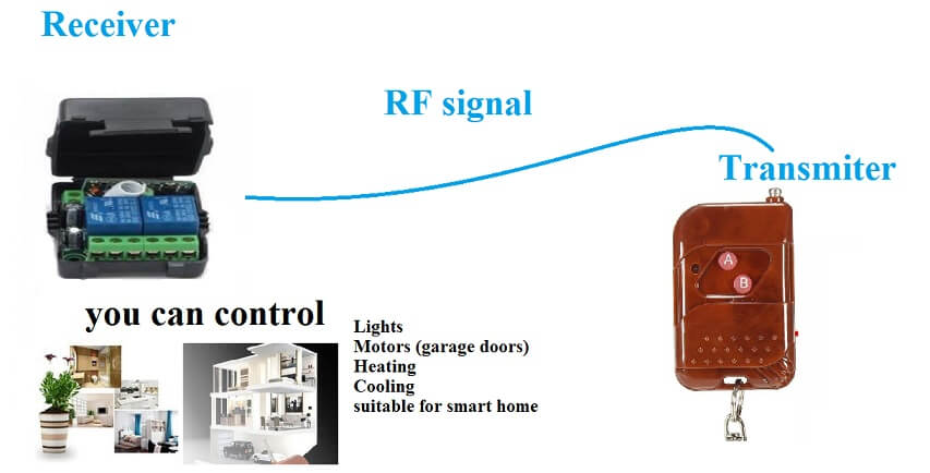
In this post I will describe a two-channel relay model KGS-B20 from szKaige manufacturer, read my review and complete instructions how to connect and set this relay
Here are the pros and cons of Kaige 12V Remote switch with two relay
Now, read my experience with a two-channel relay circuit, in my store I sold something about 230 units (at the time of writing this review) only 1 relay failed in 2 years – that’s great..
Here is pros
- PCB precision made, has two high-quality SONGLE relay
- It has a good reach, more than 90 meters in the open air
- is easy to set (see below in the manuals)
- A really good price, $ 4.5 to $ 5.5, even with a remote control
- Reliable service
- The circuit is in a black box
- You can connect multiple remote controls
- Has memory for saved remote controls
Here is cons
- The dial controller is a bit bigger, it could be smaller and different in color than the imitation of wood *
- the remote control is sold without a battery, you must then buy the A23 12V battery separately
*you can purchase other remote controls but they may not work
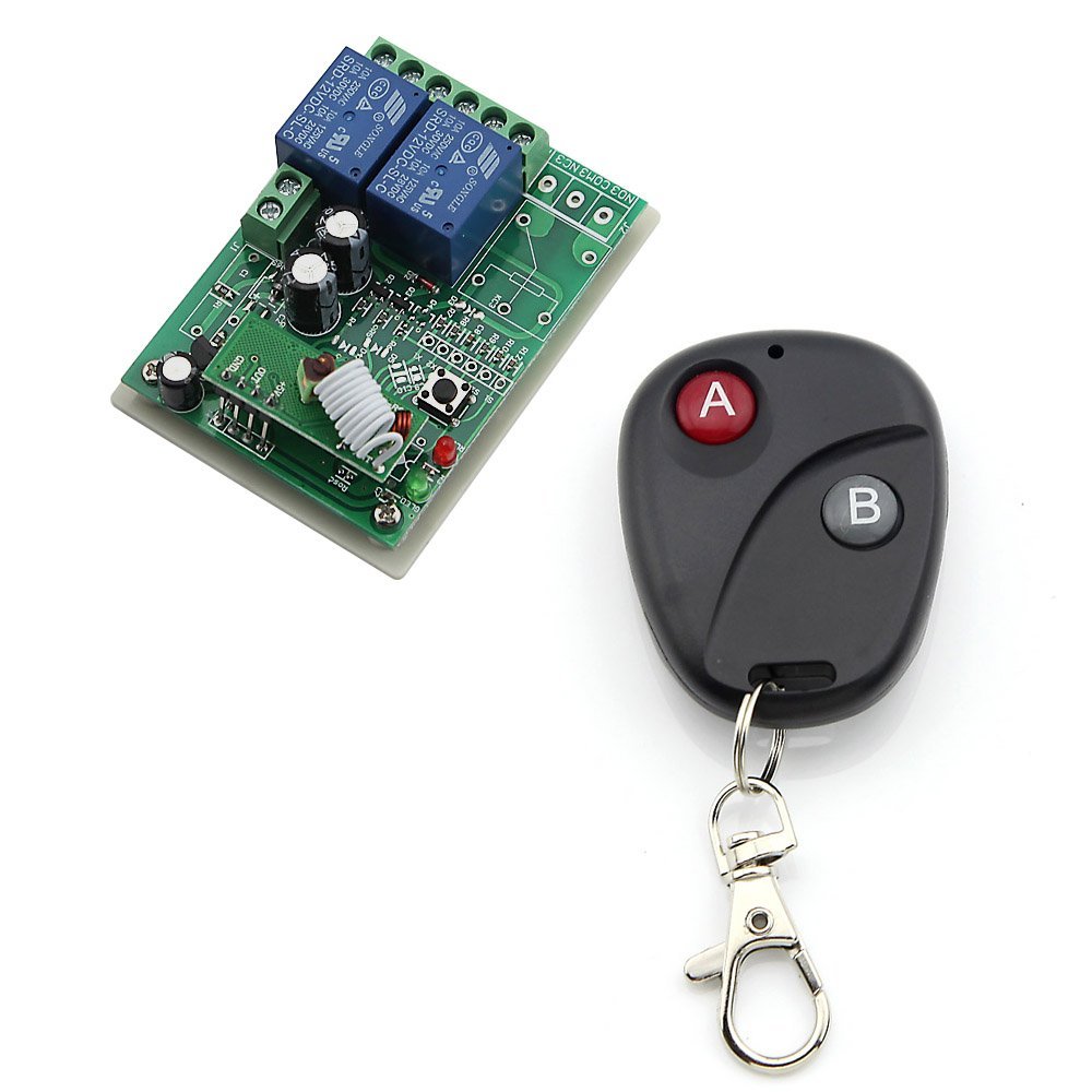
Detailed Description of Kaige two channel remote controller:
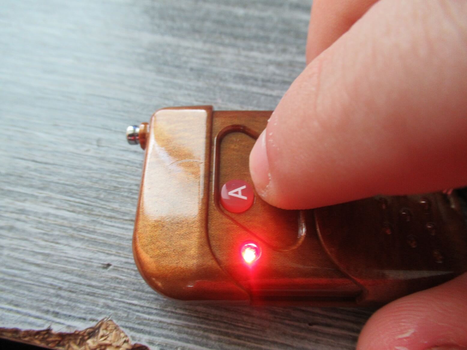
First, I’m describing the remote control – the transmitter is a brown color imitation of wood, it has two red buttons A-B (for two relays) has a telescopic antenna for a better range stretched about 5cm. Work red LED indice light while pressing the button. Operating Frequency: 315MHz but is version with 433MHz.
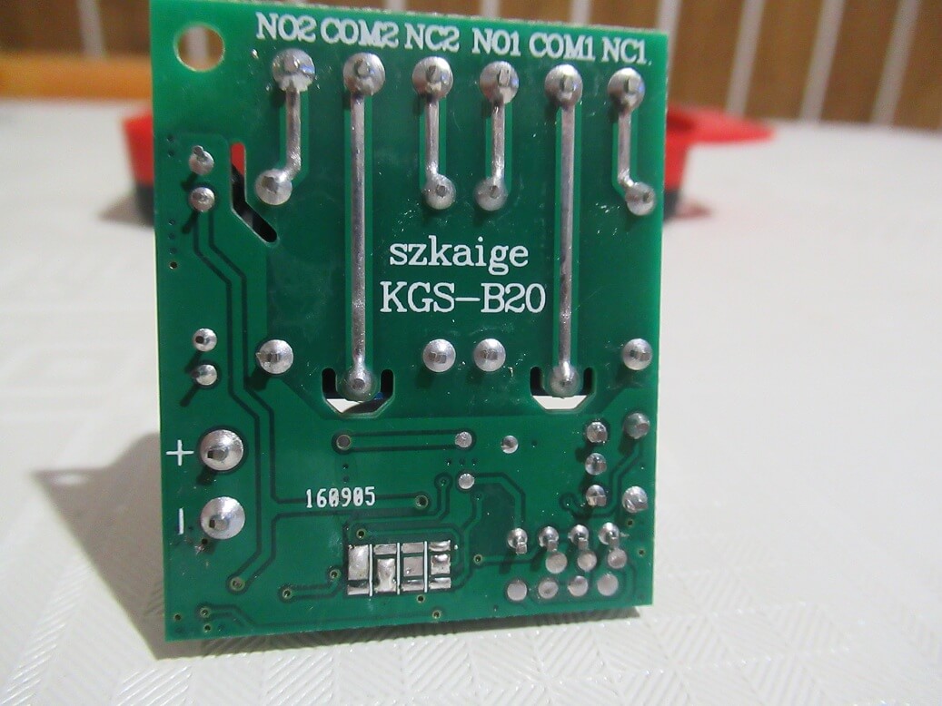
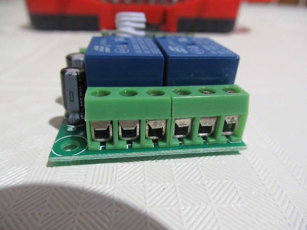 Receiver board has dark green color, is fitted with two independent Songle relay with 10A max switching power. each relay has three terminals:
- NO: COM and NO contacts are open.
- COM:Basic contact most often used for power voltage.
- NC: COM and NC COM and NC contact is connected.
Other useful componets on PCB :
- Next terminals is for 12V power is for DC 12V supply, polarity – + is indicated on the rear side of the PCB
- The white button on the side of the PCB serves to pair or unset the remote controls (in the manuals I will explain how to connect the remote control with the relay)
- JP1 switch is to set the mode of operation of the relay
- The red LED indicates the signal reception
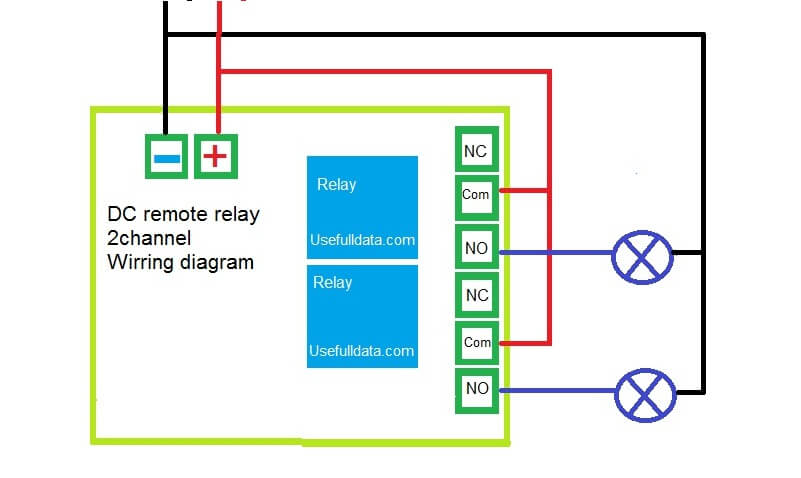
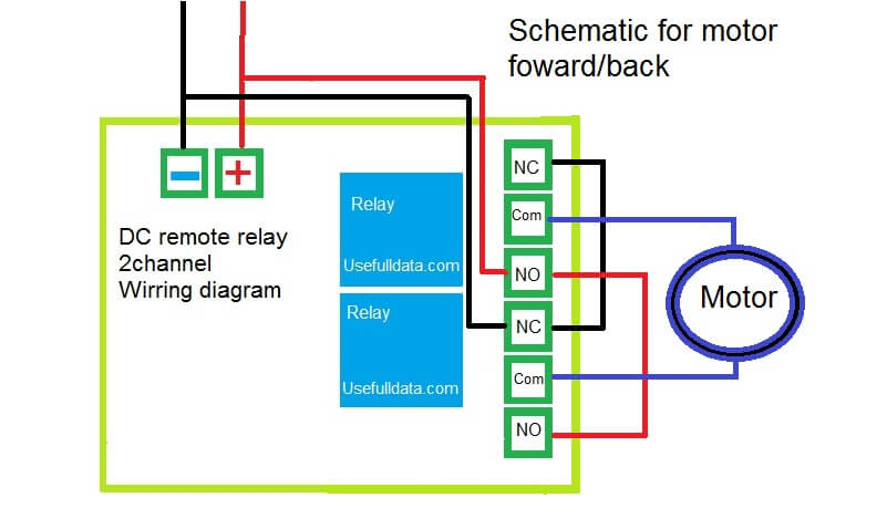
Schematic wirring diagram
useful circuits and circuits, for lighting, motors, and so on.

Great Guide manual how to pair remote controlls buttons and set receiver board mode :
Connect DC power supply 12V to receiver
Insert the 12V A23 into the remote control (if the good LED lights up on the remote control if you press the button)
 Pair and unpair remote control
If you want the remote control to work with the relay receiver here is a simple procedure:
- Press the white button on the receiver relay, the red LED lights up
- Immediately press the remote control button A on the receiver, then the red LED then release, then press the B button and then the red indicator light on the receiver will blink.
Now you have a paired transmitter with a remote controller and will work as follows for button A will operate the rele 1 and the B button will control the relay 2.
Unpair remote controll:
To remove the driver, press the for 8 second white button, the remote control will no longer work with the receiver (you will need to re-pair)
Set relay switching modes
The following lines provide instructions on how to set the relay switching modes. Use JP1 switch to set the desired mode Interlock,Jog,Self-locking
Interlock (hand press each key remote control, the corresponding relay is turned on, press another button on the remote control; the corresponding relay is turned on, the other off the first time only one relay is turned on,)
Jog (hand press each key remote control, the corresponding relay connected, release the remote control button; the corresponding relay is switched off, you can only relay turned all the way)
Self-locking, (along with a control key, press once to open, and then a close, two independent control)

JP1 has three pins 1,2,3 use a small black clutch – jumper switch here is legend how to connect pins:
- Connect pin 1 and 2: SELF-LOCK one button for one relay (first press on, second press off for each relay)
- Connect pin 2 and 3: JOG one button for one relay (hand press each key remote control, the corresponding relay connected, release the remote control button; the corresponding relay is switched off)
- Remove black jumper:Interlock mode all pins 123 is free , not connected
Here is video how to setup :
Complete technical parameters: Operating voltage: DC12V

- Working frequency: 315MHZ
- Contact capacity: ≤ 10A/250VAC; 10A/30VDC
- Receiver sensitivity:>-105dB
- Remote control distance: 50~ 100m (open area) (please stretch the antenna in order to achieve
- effective distance)
- Control approach: four normally open (normally closed) contacts
- Encoding type: fixed code; pad code
- Module size: 55mm × 40 mm× 20mm
- Work status: Self-locking
- Shock resistance: 270KRemote control parameters:
- Operating voltage: DC12V
- Operating Current: ≤ 10mA
- Operating frequency: 315MHz
- Transmission Distance: 50~ 100m (open area) (please stretch the antenna in order to achieve effective distance)
- Encoding type: fixed code; pad code
- Dimensions: 51 mm× 39mm × 13.5mm
- Oscillation resistance: 4.7m
Price and buy
Dual channel remote relay can buy from Ebay or AliExpress, good price varies around about 4-6 usd shipping includedit is a very good offer considering the possibilities of use and good performance.
The only downside is that you need to buy a 12V A23 battery good price is 1usd per piece or 2.5usd in 5 pieces
My practical tips for this relay:
- if you lose the iron clutch from JP1 jumper, you will find it old parts from PC and DVDR, HDD, Mainboard
- And if you strain + – on power, it should not matter, the device works only when properly connected +-
- The contact relay does not fit plus and minus, for example COM – minus NO – plus, when the relay activates the contacts, it makes an electrical shortcut !! – above is good wirring diagram
- If you extend the antenna, you will improve the wireless reach on the PCB
- If you want to connect a larger subscription than 10A, use a precursor contactor
- If you need more wireless drivers per PCB, no problem – just plug them up as instructed manul above
If you have questions, write them to the commentators – I’m happy to answer


")


Attachment
Hello from France dear Igor, i hope you are well,
I have a project with Arduino to build a multi-control thermostat (humidity, temperature, shielded screen keyboard and relay 2 channels and DHT22 (AM2301)…
I had never seen this kind of relay that can be controlled from a remote control.
Very nice presentation, good product thank you very much for your part and especially your help,
thanks to you I became a real cheese refiner house.
I respect you and wish you happiness. Cordially.