The Digital Multimeter is a practical tool for electrician use. It is easy to operate and the readings indicated directly on the screen. It can be use to overhaul all kinds of circuit boards. It is also an ideal teaching instrument for students.
This multi meter has been designed according to IEC -1010 concerning electronic measuring instruments with a overvoltage category (CAT n) and pollution 2.Follow all safety and operating instructions to ensure that the meter is used safely and is kept in good operating condition. Full complianca with safety standards can be guaranteed only with test leads supplied. If necessary, they must be replaced with the type specified in this manual.
If you need my experiences with this type multimeter or how calibrate voltage on multimeter please read my review
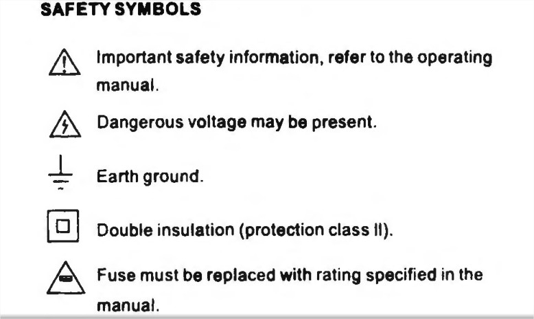
SAFETY SYMBOLS
MAINTENANCE OF MULTIMETER XL830L
• Before opening the case, always disconnect test leads from all energized circuits.
• For continue protection against fire: replace fuse only with the specified voltage and current ratings :
F 200mA/250V(Ouick Acting)
• Never use the meter unless the back cover is in place and fastened completely.
• Do not use abrasives or solvents on the meter. To clean It using a damp cloth and mild detergent only.
DURING USE
• Never exceed the protection limit values indicated in specifications for each range of measurement
• When the meter is linked to measurement circuit, do not touch unused terminals .
• Never use the meter to measure voltages that might exceed 600V above earth ground in category II installations.
• When the value sclae to be measured is unkonwn beforehand, set the range selector at the highest position .
• Before rotating the range selector to change functions ,disconnect test leads from the circuit under test.
• When carrying out measurements on TV or switching p·lwer circuits always remember that there may be high amplitude voltages pulses at test points. which can damage the meter.
• Always is careful when working w1th voltages above 60V dc or 30V ac rms . Keep fingers behind the probe barriers while measuring.
• Before attempting to insert transistors for testing. always be sure tl\at test leads have been disconnected from any measurement circuits.
• Components should not be connected to the hFE socket when making voltage measurements with test leads.
• Never perform resistance measurements on live circuits .
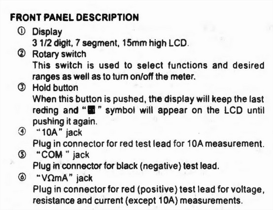
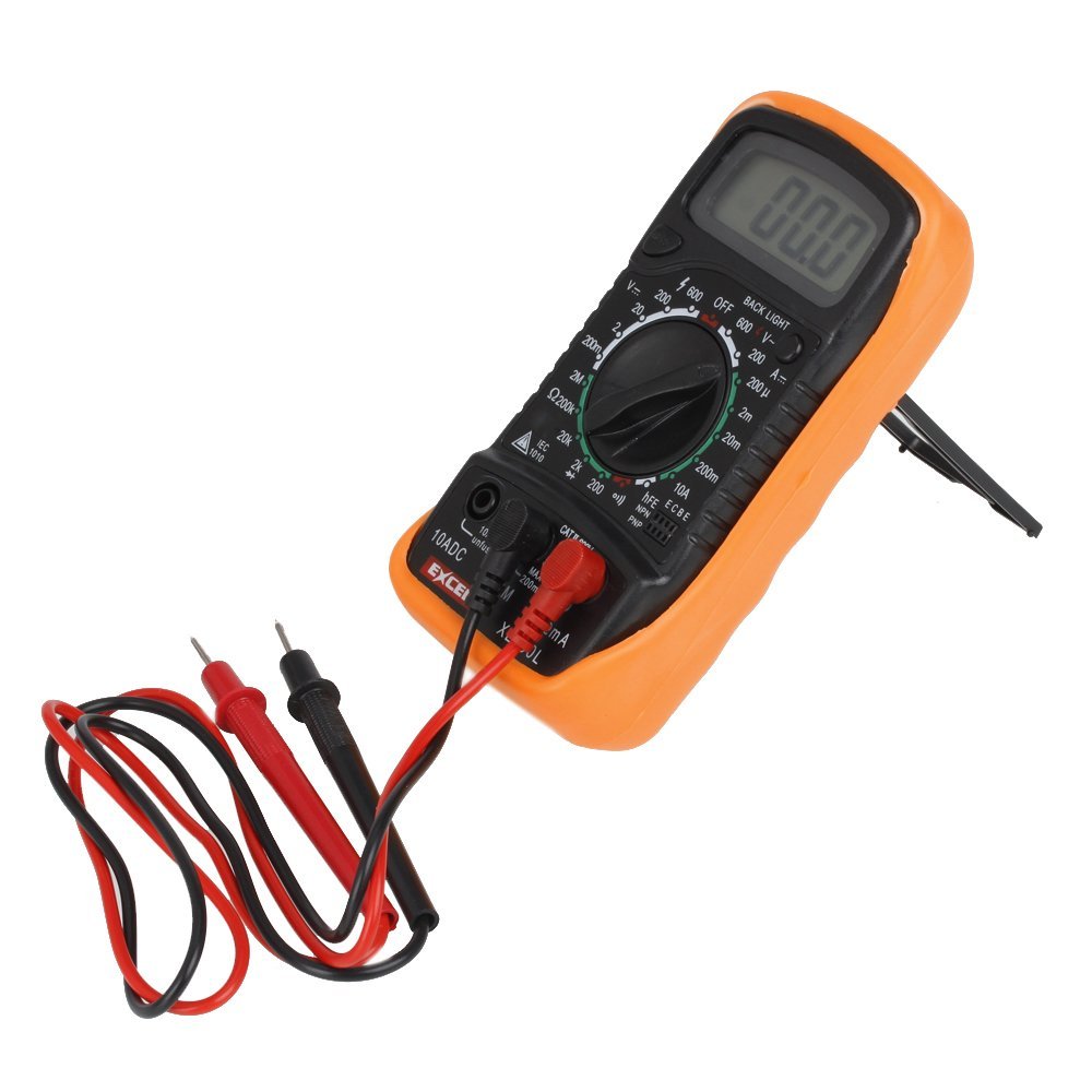
GENERAL DESCRIPTION OF XL830L MULTIMETER
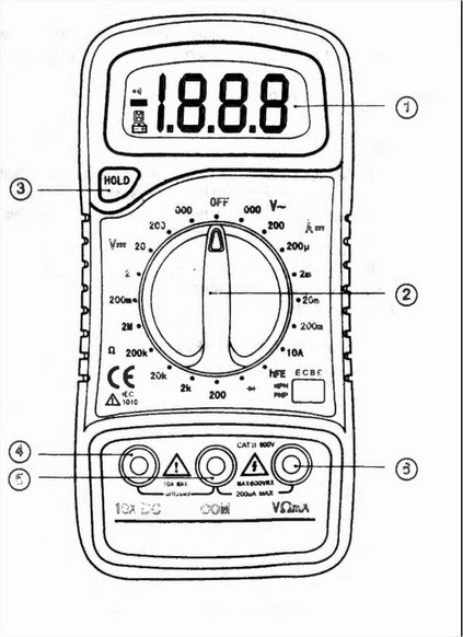
Ranges – Acurracy of Multimeter XL830L and operation instructions
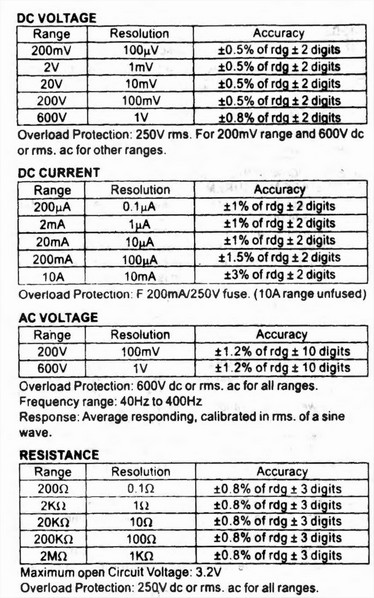
DC VOLTAGE MEASUREMENT
1. Connect the red test lead to the ” V.Q.mA” jack· and the black lead to the “COM ” jack.
2. Set rotary switch at desired DCV position, If the voltage to be measured is not known beforehand , set range switch at the highest range position and then reduce ituntil satisfactory resolution is obtained.
3. Connect test leads across the source or load being measured.
4 . Read voltage value on the LCD display along with thepolarity of the red lead connection.
CURRENT MEASUREMENT
1. Connectthe red test lead to the “V.Q.mA” jack and theblack test lead to ” COM ” jaCk. (For measurements between 200mA and lOA, remove red lead to “10 A” jack.)
2. Set the rotary switch at’ desired DCA position.
3. Open the circuit in which the current is to be measured .and connect test leads in series with the circuit
4. Read .current value on LCD display along with the polarity of red lead connection .
AC VOLTAGE MEASUREMENT
1. Connect the red test lead to ” V.Q.mA” jack and the black test lead to the ” COM ” jack.
2. Set the rotary switch at desired ACV position.
3. Connect test leads across the source or load being measured.
4. Read voltage value on the LCD display.
RESISTANCE MEASUREMENT
1. Connect the red test lead to “V.Q.mA” jack and black test lead to the ” COM ” jack. (The polarity of red lead ispositive ” +” . )
2. Set the rotary switch at desired ” !l” range position.
3. Connect test leads across the resistor to be measured and read LCD display.
4. If the res istance being measured is connected to a circuit, turn off power and discharge all capacitors before applying test probes.
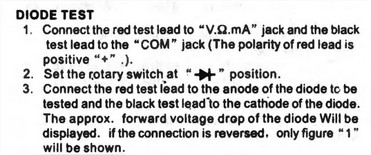
DIODE TEST
TRANSISTOR TEST
1. Set the rotary switch at ” hFE ” position.
2. Delermine whether the transistor under testing is NPN or PNP and locate the emitter, base and collector leads.
Insert the leads into proper holes of the hFE socket on the front panel.
3. Read the approximate hFE value at the test condition of base current 10 μA and Vce 3V.
NOTE: To avoid electrical shock, remove test leads from measurement circuits before testing a transistor.
BATTERY & FUSE REPLACEMENT
![]()
Fuse rarely need replacement and blow almost always as a result of operator’s error.
To replace battery & fuse {200mAI250V) remove the 2 screws in the bottom of the case. Simply remove the old, and replace with a new one.Be careful to observe battery polatity.
WARNING!!!
Before attempting to open the case, always be sure that test leads have been disconnected from measurement circuits.
Close case and tighten screws completely before using the meter to avoid electrical shock hazard.
 STANDARD ACCESSORIES
• Operator’s instruction manual
• Set of test leads
• Gift box
• 9 volt battery. NEDA 1604 6F22 006P type
• Holster (option)
Multimeter technical features and parameters
-
100% brand new and high quality .
-
The Digital Multimeter is a practical tool for electrician use. It is easy to operate and the readings indicated directly on the screen. It can be use to overhaul all kinds of circuit boards. It is also an ideal teaching instrument for students.
-
15mm high LCD Display
-
Portable and compact design, overload protection on all ranges
-
Diode assembly test/Transistor P-N junction test/Transistor HFE test
-
Continuity test with buzzer sound in circuit.
-
Low battery voltage indication
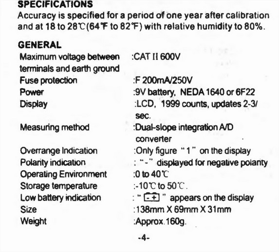
Specification of ranges and accuracy:
-
DC Voltage: 200mV/2V/20V/200V +- 0.5%, 600V +- 0.8%
-
AC Voltage: 200V/600V +- 1.2%
-
DC Current: 200¦ÌA/2mA/20mA +- 1%, 200mA +- 1.5%, 10A +- 3%
-
Resistance: 200¦Ø/2K¦Ø/20K¦Ø/200K¦Ø/2M¦Ø +- 0.8%
-
Display: LCD, 1999 counts
-
Fuse protection: F-200mA/250V
-
Operating Temperature: -0C to 40C
-
Overrange Indication: Only figure “1” on the display
-
Polarity Indication: “-” displayed for negative polarity
-
Low Battery Indication: – /+ display
-
Power by: 9V Battery(Not included)
Excel XL830L Multimeter Instructions manual

")

 diagram schematic , manual")

don’t mention the impedance of this unit
Hi
I’ve never used one of these before. I want to test xmas lights. I’ve read these instructions and it’s all a foreign language to me. It’s UK voltage so AC but I haven’t a clue what dials to set it to. I’ve got the red and black leads in the correct place but I can’t see anywhere how to set it. Any help very much appreciated!!