Good day here is my complete review , with schematic how to connect Hall proximity sensor to device CF5135B. I buy 3 pieces for start and here is my experience.In my review you see pros and cons, detailed instructions how to plug and set this device with technical parameters.
I tried to run the speedometer for about 2 hours.After two hours, I found that the device was totally wrong, I will describe my mistake below where I give the correct scheme.Now the plus and minus of the device:
Here are the pros and cons of CF5135B spedometer tachometer:
Here is pros
Nice and solid design
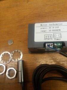
Hall sensor can be extended
The end of the sensor hall has a twisting thread with nuts
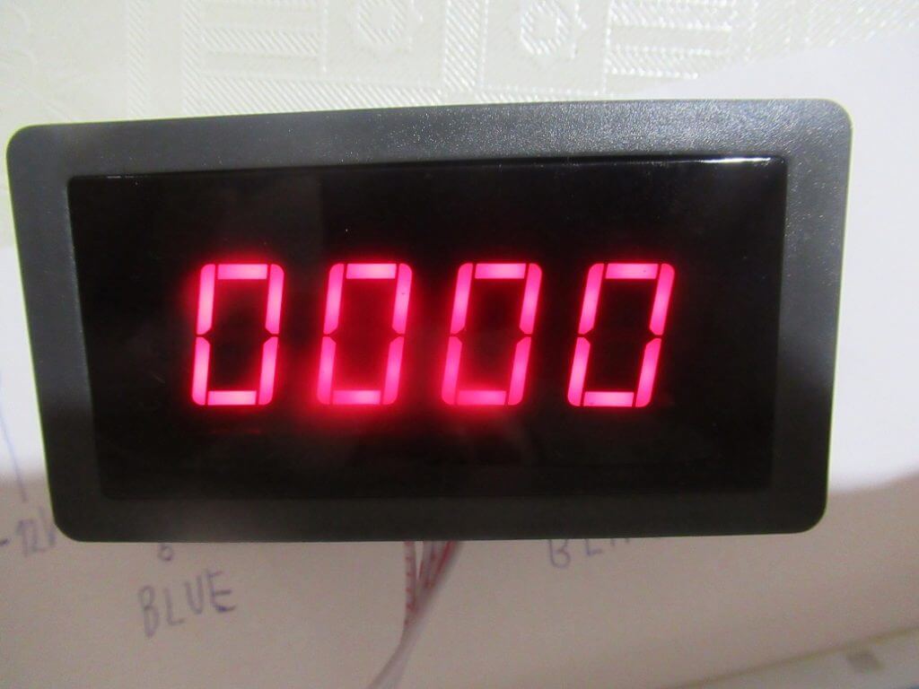
Large LED display
Maybe have protection against reverse polarity (I plugged it completely opposite and it works)
Here is cons:
Poorly labeled wires may be mistaken when connecting, I will explain below
Supply voltage is 8-24V better would be 8-30V because it can not be used in 24V cars because charging is 29V (it’s not big minus)
This product has a lot of unnecessary and just a bit different versions
Good price is under 10usd shipping include , this device can buy on aliexpress,ebay, amazon. But is carefull – watch photos closely because many types of similar to this tachometer for example with three wires yelow,red,black this review and tutorial does not describe this type
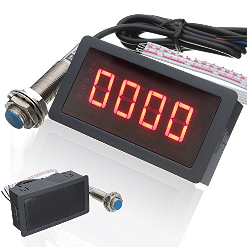
Detailed description CF5135B speedometer
Tachometer has black plastic box have clips for panel placement to electrical cabinet or other box. Display have 4 digits can buy Blue or Red its dimensions are around 67*32mm.
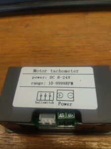
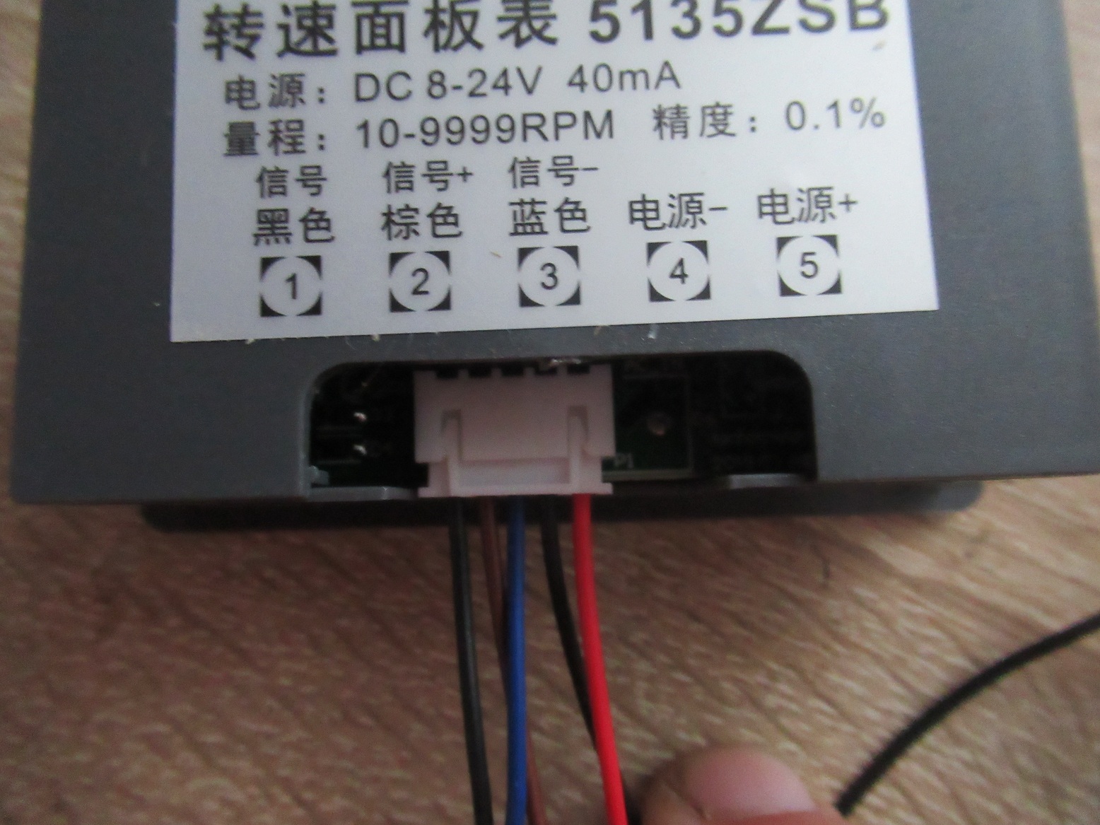
On the back of the speedometer is the range of speed measurement per minute and the range of supply voltage (8-24V) and consumption (40mA). Also the model name CF5135B and down is wiring diagram that could be better.
Complete manual and schematic diagram:
Now I will describe how to properly integrate the RPM tachometer with hall proximity sensor:
My failure was that I was badly turned the top-up display, then the order of the wires was exactly the opposite of the diagram and the device did not work (of course)
The RPM device must be rotated by the display down, then the correct wires according to the diagram on the back.
Here is a description of electrical wires on connector:
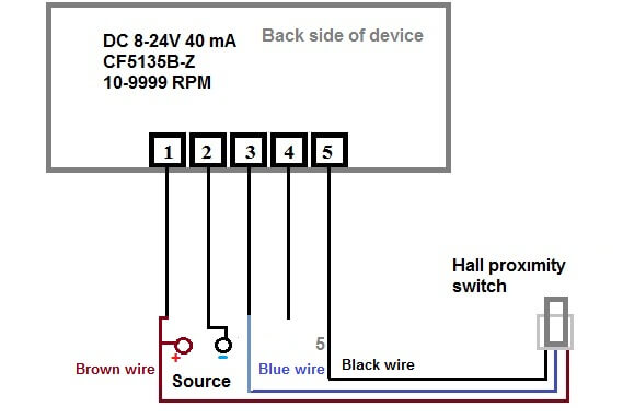
New 2024 wiring schematic:
Alternative 2021- wiring with red black
(5) Red wire + 12V to power supply
(4) Black wire – 12V to power supply
(3) Brown wire- Brown wire Hall sensor
(2) Blue wire- Blue wire Hall sensor
(1) Black wire- Black wire Hall sensor
Standard wiring:
+ the positive power pole is connected to the brown wire for the magnetic sensor
– negative power pole
speed sensor / blue wire from the sensor
Fourth position (nothing connect )
speed / black sensor sensor
these are two verified circuit diagrams:
with electrical wire connections and power sourceSchematic diagram CF5135B-z
Digital LED Tachometer RPM Speed Meter with Hall Proximity Switch Sensor NPN
Schematic for Hall proximity switch from ebay it’s like a baby is drawing it, in practice for laymen this diagram inappropriate .My schematic is better:
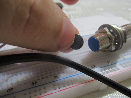
Keep in mind that the HALL probe sensor only switches when the magnet is 1-10mm away.To test the wiring, run the magnet in front of the probe mthe speedometer on the LED display will show some value.
For information, here is a description of the hall sensor switch wires:
Brown: + Source 8-24V (36V max)
Blue: – Source 8-24V
Black: Signal inpuf from Hall senzor
Hall switch is model NJK-5002C , is compatible with RPM counter CF5135B
Hi I have wired my tachometer as per your diagram and the screen lights up with 4 zeros and the light on the sensor is on but the sensor will not pick up the signal have tried three different magnets and no go what have I done wrong
Hello, using this as a tacho on a boat; but misplaced the magnet. What type of magnet should I use in its place ? I had some neodymium magnets at home but they didn’t work with the sensor.
Good day i usse about 10mm magnet 1mm-2mm is tight , smaler magnet or smaller or weaker I do not recommend , magnet can buy on aliepress ebay price is about 1usd http://s.click.aliexpress.com/e/bpbVz9fE
Hello I have this all wired up the same as yours but when I turn on my motor the display only shows dashes across the screen. When I turn the motor off it goes back to zeros?
But when I rotate the spindle buy hand it works fine?
Any suggestions?
Mine had to have the magnet with North towards the sensor.
turn the magnet over and see if that helps.
Also mine wouldn’t work well with 9v, 12 volts made it work good.
Probably noise from the VFD. Keep the tacho wiring well away from the VFD leads. If possible use shielded wiring for the tacho (and the VFD if you can be bothered). You could also try wrapping the tacho power wiring around a ferrite core numerous times (close to the tacho) to reduce noise. Shield the wiring from the proxy if possible, keep it short and keep it away from the VFD and see if that helps. Have the proxy mounted on an Earthed metal plate if possible (e.g. an Earthed Aluminium bracket). Ensure the Motor is very well Earthed and if possible use proper shielded and Earthed VFD cable. .
Hi,
I bought two, they worked in the beginning and when I mounted them on the Tractor with an extension of the cable, they both did not work anymore. There is no display and at the interrupter the control lamp does not burn anymore. Why? I fed them with a 9V battery.
A 9 volt battery doesn’t necessarily give you 9 volts of power. As you are already close to the minimum operating voltage of the device, that could be the problem.
I’m just guessing, but I would try doubling the batteries so you get ~18 volts.
this thing is so badly designed….i discovered that mine refuse to pick up the signal from the sensor below 12vdc….signal passes thru a voltage divider, two diodes and then sent to the tiny mcu. there are empty places on the pcb to install a npn transistor to buffer the signal properly ie independent of the voltage supply then…could have been nice to explain/tell the usage of the non-installed buttons….hidden features ? also a ratio divider/programmable could be usefull where you need to install two magnets 180 deg apart to avoid vibration in sensitive high speed machine. hth. your diagram helped me understand how to make its basic wiring. chineese symbols are not helpfull for the wwm
by togling K4 it changes from hertz, counter and rpm meter so it is helpfull…there might be other modes that i cant tell from the two other switches.
coorect mode for RPM meter is SE-3
I have a machine with 4 magnets already on the shaft will it work with this, is there a switch for setting the reading to divide by 4, to allow it to display
the correct RPM on the LED display.
I am using the tachometer on a drive pulley. On the other end of the shaft is a driven pulley which changes diameter with each test. It is the driven RPM i am seeking to measure. Where do I connect a potentiometer to this meter so that I can calibrate the meter to the driven RPM? What would be the value of this pot? Hall sensor can be connected to the drive pulley ( set diameter ) however it cannot be mounted to the driven pulley because the driven pulley changes often, and the diameter is different each time. A calibration potentiometer will allow us to adjust for different diameter driven pulleys.
Hi
Mine displays four dashes as soon as I start the 3 phase motor as well – did anyone confirm the cause of this? I am running it on 12 volts and in the process of shielding the wiring but have not cured this as yet. have seen the responses on this but wonder if anyone can confirm the cure for it, many thanks
 Complete manual and schematic diagram:


 My schematic is better:
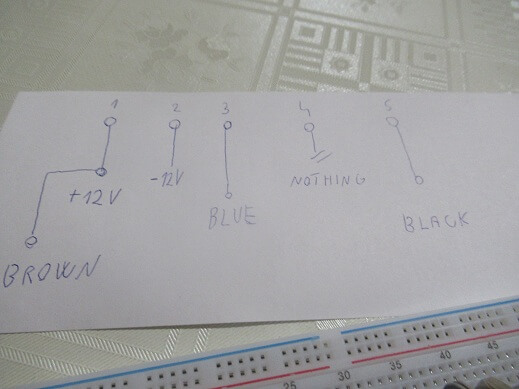
 Keep in mind that the HALL probe sensor only switches when the magnet is 1-10mm away.To test the wiring, run the magnet in front of the probe mthe speedometer on the LED display will show some value.
 Blue /Red 4 Digital LED Tachometer RPM Speed Meter+Hall Proximity Switch Sensor NPN
 diagram schematic , manual")

 diagram schematic , manual")


Can i use this setup like a counter and not as a rpm?
Hi device show only actual RPM
Hi I have wired my tachometer as per your diagram and the screen lights up with 4 zeros and the light on the sensor is on but the sensor will not pick up the signal have tried three different magnets and no go what have I done wrong
your wiring schematic is best on the web..thanks
Hello, using this as a tacho on a boat; but misplaced the magnet. What type of magnet should I use in its place ? I had some neodymium magnets at home but they didn’t work with the sensor.
Good day i usse about 10mm magnet 1mm-2mm is tight , smaler magnet or smaller or weaker I do not recommend , magnet can buy on aliepress ebay price is about 1usd
http://s.click.aliexpress.com/e/bpbVz9fE
Hello I have this all wired up the same as yours but when I turn on my motor the display only shows dashes across the screen. When I turn the motor off it goes back to zeros?
But when I rotate the spindle buy hand it works fine?
Any suggestions?
Maybe fail communication between panel board and sensor or maybe RPM is higger as 10 000 ? (10,000 is quite a lot)
Mine too – I’m using a single to three phase VFD? Wonder if the proximity to the inverter is to blame?
Mine had to have the magnet with North towards the sensor.
turn the magnet over and see if that helps.
Also mine wouldn’t work well with 9v, 12 volts made it work good.
Probably noise from the VFD. Keep the tacho wiring well away from the VFD leads. If possible use shielded wiring for the tacho (and the VFD if you can be bothered). You could also try wrapping the tacho power wiring around a ferrite core numerous times (close to the tacho) to reduce noise. Shield the wiring from the proxy if possible, keep it short and keep it away from the VFD and see if that helps. Have the proxy mounted on an Earthed metal plate if possible (e.g. an Earthed Aluminium bracket). Ensure the Motor is very well Earthed and if possible use proper shielded and Earthed VFD cable. .
Hi,
I bought two, they worked in the beginning and when I mounted them on the Tractor with an extension of the cable, they both did not work anymore. There is no display and at the interrupter the control lamp does not burn anymore. Why? I fed them with a 9V battery.
Maybee wrong wirring can you remove back ?
A 9 volt battery doesn’t necessarily give you 9 volts of power. As you are already close to the minimum operating voltage of the device, that could be the problem.
I’m just guessing, but I would try doubling the batteries so you get ~18 volts.
Thanks for info , i test on 12V all work ok
Can I extend the sensor wire as it could be a bit short
Yeas of course
Hi, is possible instead of using Hall proxinity sensor to take the signal form ignition coil? Does it works?
Ignition coil has big voltage probaly destroy electronics
this thing is so badly designed….i discovered that mine refuse to pick up the signal from the sensor below 12vdc….signal passes thru a voltage divider, two diodes and then sent to the tiny mcu. there are empty places on the pcb to install a npn transistor to buffer the signal properly ie independent of the voltage supply then…could have been nice to explain/tell the usage of the non-installed buttons….hidden features ? also a ratio divider/programmable could be usefull where you need to install two magnets 180 deg apart to avoid vibration in sensitive high speed machine. hth. your diagram helped me understand how to make its basic wiring. chineese symbols are not helpfull for the wwm
by togling K4 it changes from hertz, counter and rpm meter so it is helpfull…there might be other modes that i cant tell from the two other switches.
coorect mode for RPM meter is SE-3
I have a machine with 4 magnets already on the shaft will it work with this, is there a switch for setting the reading to divide by 4, to allow it to display
the correct RPM on the LED display.
I have the unit but need to know how to use it to check the RPM on a Suzuki 250 quad king 4 wheeler
Attachment
Hi Ivan,
I am using the tachometer on a drive pulley. On the other end of the shaft is a driven pulley which changes diameter with each test. It is the driven RPM i am seeking to measure. Where do I connect a potentiometer to this meter so that I can calibrate the meter to the driven RPM? What would be the value of this pot? Hall sensor can be connected to the drive pulley ( set diameter ) however it cannot be mounted to the driven pulley because the driven pulley changes often, and the diameter is different each time. A calibration potentiometer will allow us to adjust for different diameter driven pulleys.
Thank You
Dean
Hi
Mine displays four dashes as soon as I start the 3 phase motor as well – did anyone confirm the cause of this? I am running it on 12 volts and in the process of shielding the wiring but have not cured this as yet. have seen the responses on this but wonder if anyone can confirm the cure for it, many thanks
I got exactly the same thing. works fine on a drill press, will not work on the 3P lathe.