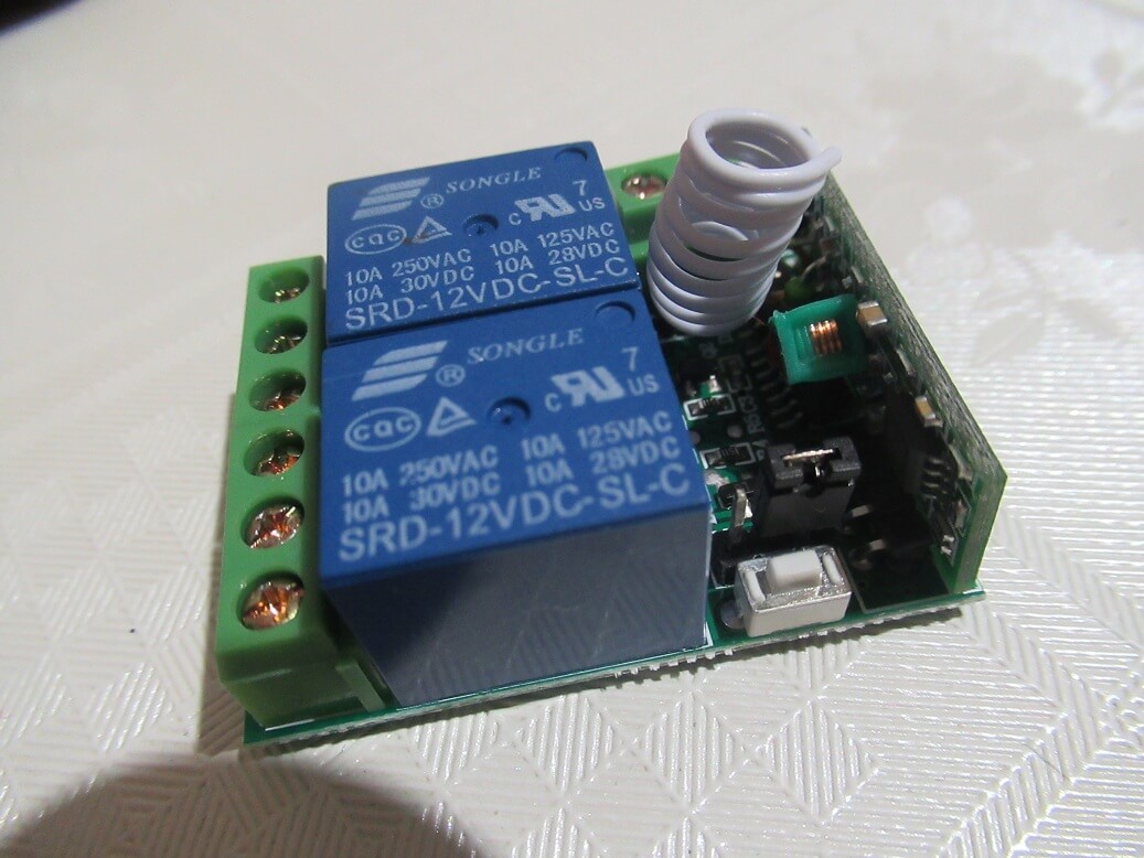
In this post I describe a two-channel remote relay switch with power source 220V. Now read my review and complete instructions how to connect and set this relay module.
- Maybee you need good remote relay switch on 12V with 2 channel check it
Here are the pros and cons of 220v Remote switch with two relay
Here is pros:
- It has a box that protects the electronics
- Good price considering the function that offers a remote-controlled relay
- Good range of remote control about 60 m
- 2 relays can control two different devices if required
Here is cons
- In the beginning it can be difficult to set a relay modes
- The remotes some vendors not give 12V A23 alkaline battery (you have to buy separately)
- Be carefull high voltage can be after power off.. but is normal on voltage 220V.
Remote control:
Remote control have black case with two butons. Buttons A and B control individual relay on PCB.
Press buton on remote control the relay on or off (how is seting on pcb board). Red LED indicating the pressing of buttons respectively transmitted signal. To control work is necessary to ensure power supply with 12V A23 battery (It costs about 1 USD).
The instructions manual below to learn how to pair your controller with relay
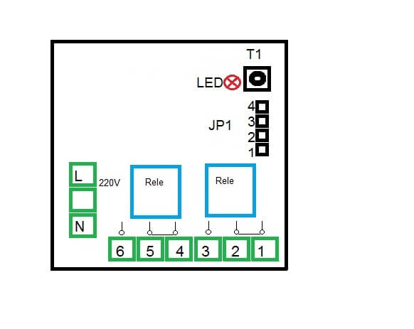
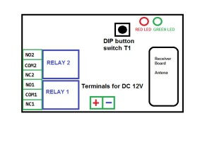
PCB is very similar as 12V version this relay diference is on JP1 switch on 220V version.
Schematic and detailed description of module:
Basic schematic:

- Source terminals L phase N neutral (can change)
- Relay terminal relay (456 and 123)
- Red LED
- PCB button switch T1
- JP1 jumper switch for mode change.
Power should be either 220V DC voltage from the transformer or battery. The illuminating green LED indicates that the device is OK.
Two relays switch have three terminals, COM 5 and 2 midle terminal .NO – (Normaly open) 6 and3 , NC (Normaly closed) 4-1. If you press on the remote control, NC opens and closes the NO. (other features based on the selected mode)
Technical data:
- Input Voltage: DC 220V
- Operating Frequency: 433Mhz
- Operation Way: Inching, Self-locking, Interlocked
- Coding Way: Intelligent Learning
- Output Type: Passive Output
- Max load: 10A
- Ambient TEMP: -20℃ -65℃, Humidity<95%
- Factory Default: Self-locking
- Board DIM: 69x49x17mm
- Case DIM: 75x65x29mm
Transmitter
- Operating Voltage: DC 12V
- Operating Frequency: 433Mhz
- Vibration Resistance: 126
- Chip Type: 2260
- Modulation: ASK (Stable, less interference)
- Encode Type: Welding code
- Battery Type: 12V 27A(not included)
- Remote Distance: 20m (Theoretical value)
- Ambient TEMP: -30℃ -70℃ , Humidity<95%
- Product DIM: 50x39x12mm
How to set relay switching modes
To set the mode, use the JP1 switch (jumper), the jumper position changes only when the 220V supply voltage is turn OFF otherwise the relay will work according to the old mode
The T1 button is used to pair the receiver relay (circuit board with two relays) and the remote (transmitter).
How Add the remote control
- press the T1 button – the red LED on the remote control comes on
- press A followed by the B keys.
To erase the remote control, press the T1 button for 3-4 seconds. The red LED flashes, wait until it stops – the remote control is turned off.
How to set modes
The Mode 1 – JP1 jumper connects contacts 1 and 2. The receiver relay contacts closed only when the button on the remote control is held.
The Mode 2 -JP1 jumper connects contacts 3 and 4. The relay on the receiver will closed for first touch button after again touch buttor relay is OFF. on until the button is pressed again on the remote control.
Remove the jumper mode3 JP1, hat no connected any contact. When the A button is pressed, one relay opens on the receiver and the other relay1 closed and relay 2 open. After push button B, the first relay will open and the second will close.
If you want to ask or relay experience, please send a comment…

